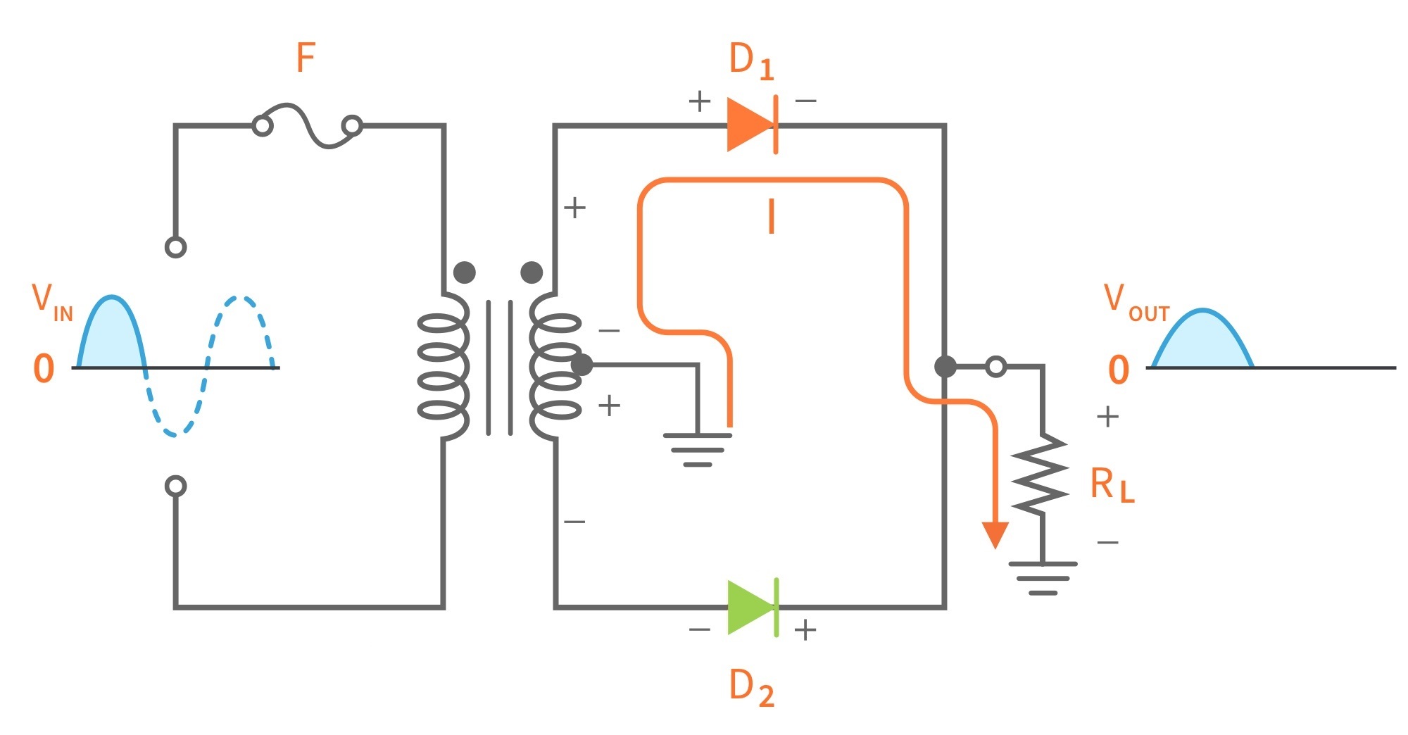
Rectifier circuit diagram Rectifier tapped transformer diode output capacitor regulator Rectifier wave full tapped center ratio turn current cycle positive path figure voltage negative daenotes
Centre Tap Full Wave Rectifier Circuit operation,Working,Diagram,Waveform
Rectifier tapped transformer voltage diodes ppt diode load equations
Difference between full wave bridge rectifier and full wave center tap
What are full-wave rectifiers? definition, centre-tap full-waveRectifier rectifiers Rectifier wave full tap centre waveforms diagram circuit waves waveform circuits electronicsDiode rectifier diagram.
Rectifier wave full circuit bridge voltage output working transformer tapped centre across load advantages consistsCenter tapped full wave rectifier : circuit and applications Center tap transformer circuitCenter tapped full wave rectifier.

Full-wave controlled center-tap rectifiers
Rectifier tappedRectifier tapped wave cycle The center-tapped full-wave rectifierRectifier tapped voltage peak figure.
Center-tapped full-wave rectifier operation -…Centre tap full wave rectifier circuit operation,working,diagram,waveform Rectifier transformer tapped output waveform inputCenter-tapped full-wave rectifier operation -….

Wave full rectifier circuit tap centre tapped figure rectifiers bridge electronics representation shows below
Rectifier voltage waveform circuits groundCenter wave full controlled tap rectifier circuit load rl rectifiers current fwd voltage figure Centre tap full wave rectifier circuit operation,working,diagram,waveformCentre tap rectifier circuit 1.
Tap circuit transformer centre center rectifier multisimRectifier tapped voltage inverse Centre tap full wave rectifier circuit operation,working,diagram,waveformFull wave rectifier.


