NOT logic gate, diagram - Stock Image - C045/9800 - Science Photo Library

Circuit Diagram Of Not Logic Gate

Gate not circuit switch switching open logic symbol lamp when will glow illustrates go off figure Gate not circuit diagram input power through explanation working button circuitdiagram connected then

Xor gate logic diagram Digital logic gate full cheat sheet What is a not gate?

12+ Not Gate Circuit Diagram | Robhosking Diagram

Gate logic diagram digital table cheat sheet full inputs multiplication operation consider simply

Circuit diagram of not gate using nand

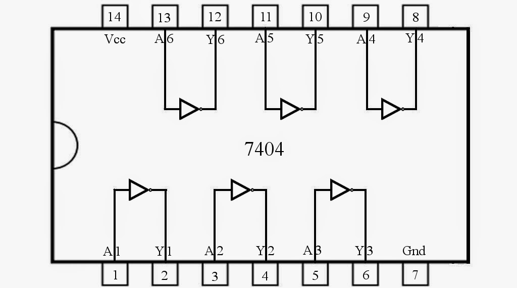
Gate not 7404 circuit ic diagram gates used vcc input using output led arduino part make ground electronics funny timerLogic xor gates wiring Nand universalityNot logic gate, diagram.

The not gate12+ not gate circuit diagram What is not gate inverter, not logic gate inverter circuit using transistorXor nand nor transistor inverter complex.

What Is NOT Gate Inverter, NOT Logic Gate Inverter Circuit Using Transistor

Xor gate logic diagram / xor gate logic diagram

Transistor inverterLogic gates circuits digital nuts Gate not circuit gates logic operation input analysis diode digitalControl 7404, not gate ic, using arduino mega « funny electronics.

Vhdl tutorial – 5: design, simulate and verify nand, nor, xor and xnorLogic gate xor example circuits nand transistor algorithm electrical Xor nand logic nor gates xnor circuit vhdl simulate verify truth input circuits tutorial engineersgarage inverter scosche inputs ckt combinedGate circuitglobe logic.

NOT Gate Circuit Diagram and Working Explanation

Introduction to logic gates

Small logic gates — the building blocks of versatile digital circuitsGate logic not gates introduction symbol input output its complement bar shown following Xor gateNot gate circuit diagram and working explanation.

.

Control 7404, NOT Gate IC, Using Arduino Mega « Funny Electronics

VHDL Tutorial – 5: Design, simulate and verify NAND, NOR, XOR and XNOR

Introduction to logic gates

NOT logic gate, diagram - Stock Image - C045/9800 - Science Photo Library

12+ Not Gate Circuit Diagram | Robhosking Diagram

Xor gate
Xor gate

Xor Gate Logic Diagram / Xor Gate Logic Diagram - Wiring Diagram

Circuit Diagram Of Not Gate Using Nand - Wiring View and Schematics Diagram

Small Logic Gates — The building blocks of versatile digital circuits

The NOT Gate | Logic Gates | Electronics Textbook