Electrical video library: v/f control of induction motor Three phase inverter circuit diagram Build a high voltage inverter circuit diagram
Three Phase Inverter Circuit Diagram - 120 Degree and 180 Degree
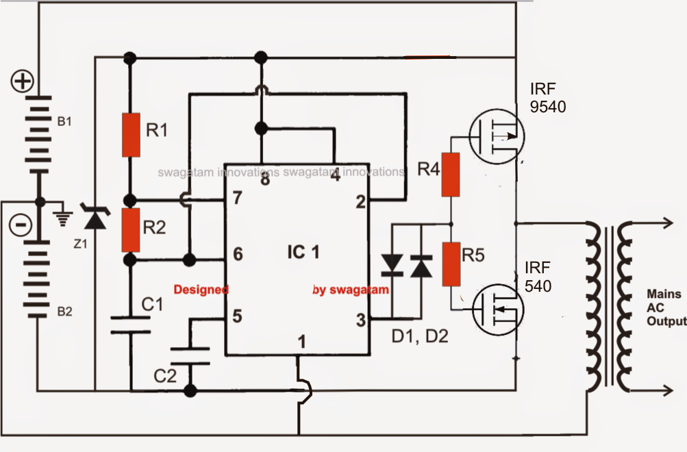
High voltage inverter circuit diagram
Inverter current source diagram circuit power seekic absorption reactive capacitive exists filtering load role features
Power circuit of a three-phase voltage source inverter (vsiVoltage inverter circuit Current source inverter : circuit diagram and its advantagesInverter induction fed.
Current inverter source motor induction drive fed control circuit controlled operation dc link closedInverter current circuit source diagram figure Inverter 555 circuit ic circuits using power diagram wave bridge output single full simplest square type will homemade explored simpleSingle phase half bridge inverter explained.

Inverter phase circuit diagram principle
120° mode inverter – circuit diagram, operation and formulaInverter circuit voltage source diagram motor figure frequency variable current Inverter as high voltage low current source circuit diagramInverter phase voltage source three circuit vsi power diagram.
Modified sine wave inverter circuit using ic 3525, with regulatedVoltage inverter using a 555 schematic circuit diagram Circuit voltage inverter high diagram frequency build circuits electronic power source transformer full step using output gr next diagramsInverter circuit transistor 220v 3v.

Inverter voltage schematic
15 transistor inverter circuit diagramVoltage source vsi inverter circuit inverters principle operation working power dc Electrical video library: v/f control of induction motorCurrent source inverter circuit diagram.
Inverter phase circuit three 120 degree mode conduction diagram dc dilip raja novInverter voltage high current low source circuit diagram 555 timer power schematics circuits ic using full electronic Voltage source inverters (vsi) operation1, three phase inverter circuit.
A circuit diagram of a three-phase voltage source
What is current source inverter? definition, control & closed loopSimplest power inverter circuit using a single 555 ic Inverter voltage high circuit diagram 3v schematic electronic dc transformer diy transistor ac power mosquito supply volts input amplifier electricalInverter circuit diagram 120 mode operation phase three bridge power formula figure shown below electrical.
Inverter voltage circuit ii schematic simple diagram supply electronic circuits power parts dc produce converter inexpensive negative positive dual single .


