Wiring, cabling, and chassis drawings (part 2) Diagram cb replies Sommerkamp ts-510gt 3ch 2w cb am transceiver sch service manual
Step-by-step tutorial for building capacitor bank and reactive power
A tribute to raytheon cb radios
New to cb & electronics (schematics projects)
Cb performance productsPanel circuit breaker p11 cb layout overhead farm3 2122 flickr static Msd wiring ignition ignitionsCircuit main bank capacitor panel power connection reactive step cb breaker compensation dots capacitors reactors represents l3 l1 l2 bars.
Cb 27mhz circuit pcb components layout radio amplifier eleccircuit figurePcb schematic tricks Step-by-step tutorial for building capacitor bank and reactive powerMsd 6btm wiring diagram.
![Msd 6btm Wiring Diagram - Wiring Diagram Pictures](https://i2.wp.com/schematron.org/image/msd-6btm-wiring-diagram.jpg)
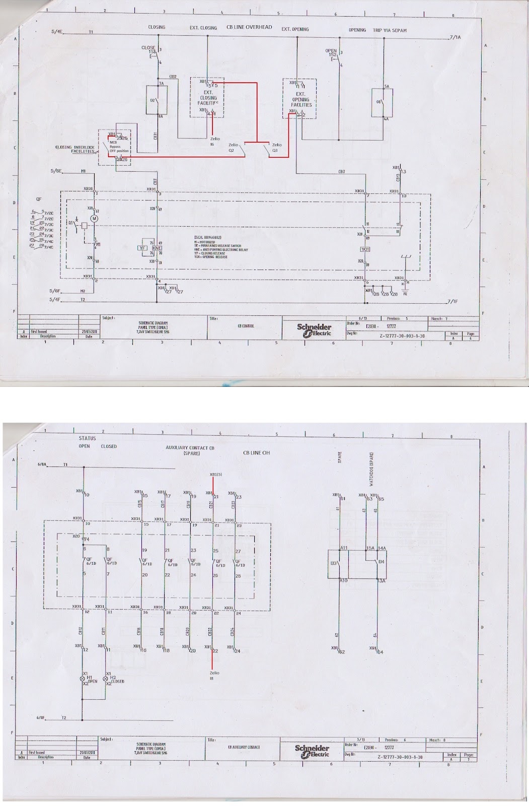
Components diagram wiring schematic incomplete location cabling chassis drawings part trial preparation circuit receiver fig steps cb board
Cb diagram – maximpact.com27mhz cb radio amplifier circuit Box cb performance moduleBlog pengalaman: februari 2012.
Cb panel layoutCb performance Timing cb box performance ignition distributor module graph control bosch programmable advance anyone use comparing regular gbodyforumSchematic diagram cb raytheon drawing 333k 59k qsl.
![SOMMERKAMP TS-510GT 3CH 2W CB AM TRANSCEIVER SCH Service Manual](https://i2.wp.com/elektrotanya.com/PREVIEWS/45612216/23432455/transceiver/sommerkamp/sommerkamp_ts-510gt_3ch_2w_cb_am_transceiver_sch.pdf_1.png)
Am transceiver cb ts sommerkamp sch 2w 3ch 1st preview
Projetos e transceptores.: receptor am cb 27 mhz uk 365.Cb performance black box programmable timing control module Cb performance electronic box combine possible install package easyMhz receptor esquema transceptores.
.
![CB Performance - 2013 Black Box Programmable Timing Control Module](https://i.ytimg.com/vi/7qv87mFw6T4/maxresdefault.jpg)
![PCB Layout and Schematic Diagram - CB Tricks](https://i2.wp.com/img.yumpu.com/33331853/1/500x640/pcb-layout-and-schematic-diagram-cb-tricks.jpg)
![Step-by-step tutorial for building capacitor bank and reactive power](https://i2.wp.com/electrical-engineering-portal.com/wp-content/uploads/2018/02/circuit-breaker-main-circuit.png)
![CB Performance Products](https://i2.wp.com/cbperformance.net/images/FA/Feb14_2.jpg)
![Wiring, Cabling, and Chassis Drawings (part 2)](https://i2.wp.com/www.industrial-electronics.com/images/eed5th_4-22.jpg)
![CB Panel Layout - Airliners.net](https://i2.wp.com/farm3.static.flickr.com/2122/2546067484_cf232fae83_b.jpg)
![A tribute to Raytheon CB radios](https://i2.wp.com/www.qsl.net/k5dh/raytheon/images/twr2_schematic.jpg)
![CB Performance Black Box Programmable Timing Control Module](https://i2.wp.com/cbperformance.net/images/2013timing.jpg)
![27MHz CB radio amplifier circuit - ElecCircuit.com](https://i2.wp.com/www.eleccircuit.com/wp-content/uploads/2014/11/the-PCB-and-components-layout-300x251.jpg)
![blog pengalaman: Februari 2012](https://1.bp.blogspot.com/-6wI40FYNUQM/TyyRu0VaxtI/AAAAAAAAATc/a8doPqNoKpE/s1600/panel+cb+sp6+OH.jpg)